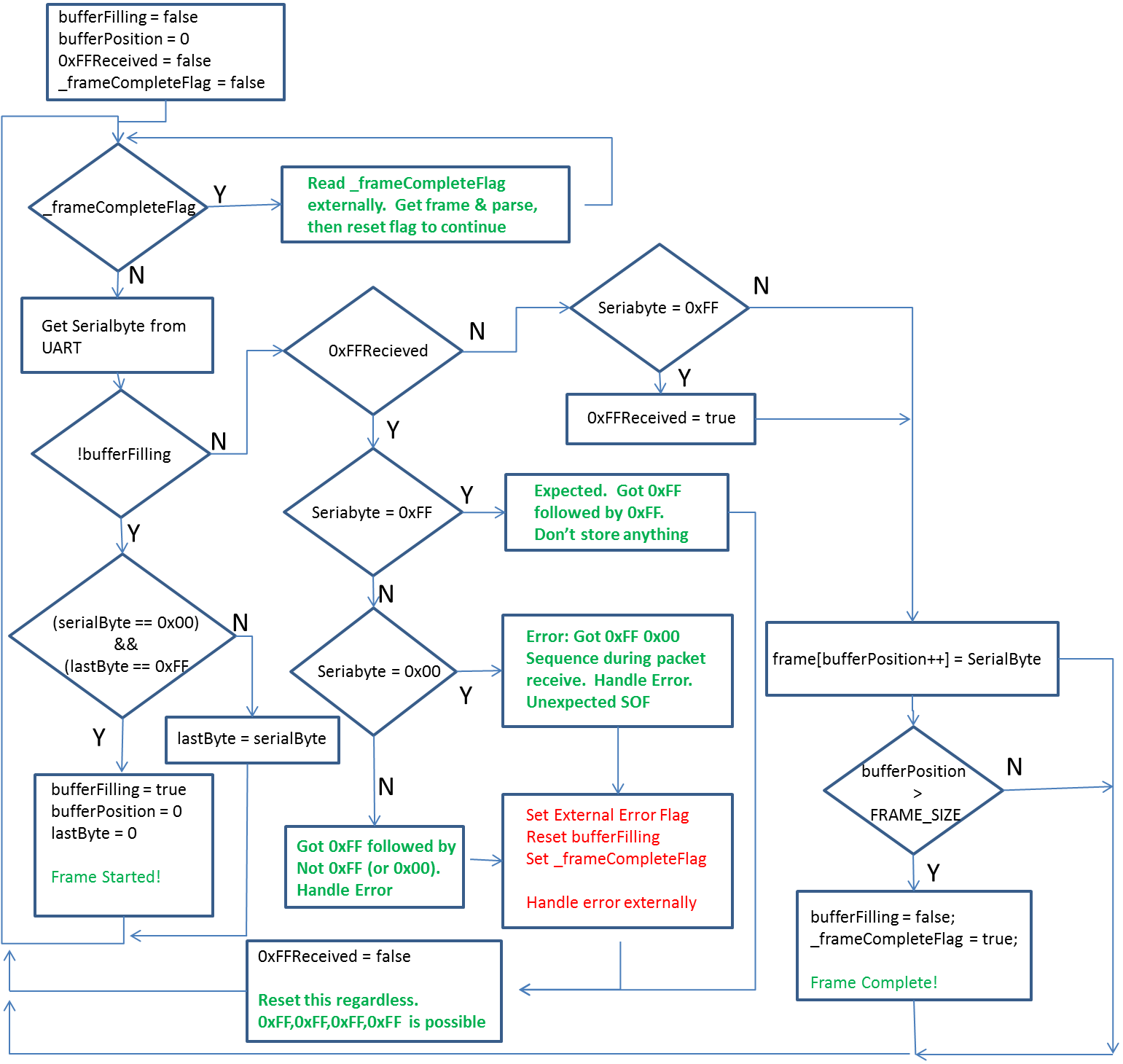
It’s data time! As discussed last time, the data comes in a standard serial stream at 62500 baud and no parity, 8 bits, 1 stop bit (62500,n,8,1). Each frame starts with the 2-byte sequence 0xFF, 0x00 and then the individual bytes of serial data. One situation to be aware of is when the data within the packet match this sequence(0xFF,0x00)…it’s not just possible, it happens all the time. To manage this case, the ECU sends a second 0xFF after the first to indicate that the first one is valid data and a start of frame sequence (SOF) is not underway. Therefore, whenever a packet is being received and a 0xFF is received, always check for another 0xFF behind it.
Example Frame
| 0xFF | Start of Frame Sequence |
| 0x00 | |
| 0x30 | Data 1 |
| 0x64 | Data 2 |
| 0x17 | Data 3 |
| 0xFF | Look for another 0xFF |
| 0xFF | Got it, Data 4 |
| 0x00 | Data 5 |
| .. | |
| 0xXX | Last Data |
Each data frame packet from my ECU is 28 bytes + 0xFF, 0x00, for a total of 30 bytes. Below is the rough logic flow for analyzing the byte-wise stream of data as it comes in.
Once a frame is received, it can be parsed into the different ECU variables. Here is frame data as I know it:
framebuffer[0] – ECU Program Version (Constant)
framebuffer[1] – ECU PROM version (Constant)
framebuffer[2] – Calibration Code from engine
framebuffer[3]/9.13) + 3.1 – inches of Hg
framebuffer[4]/0.888) – 40 – Coolant Temp Sensor in F
framebuffer[5]/0.888)-40 – Inductive Air Temp F
framebuffer[6]/16.24 – Charging Voltage Vdc
framebuffer[7]/51.2 – O2 Sensor reading in volts (0 = Rich, 5 = Lean)
frameBuffer[9] << 8) | (frameBuffer[8]))/19850000 – Engine RPM
frameBuffer[10] – PROM 1
frameBuffer[11] – PROM 2
frameBuffer[12] / 2.55 – Throttle Position Sensor (% Open)
frameBuffer[13] – Spark advance in degrees
frameBuffer[14] – Unknown
frameBuffer[15] – Unknown
frameBuffer[16] / 9.3) + 3.1 – Initial Manifold Absolute Pressure inches Hg
frameBuffer[17] – Unknown
frameBuffer[18] – Bits indicate fuel control mode (open/closed) and if we’re in rich or lean condition
frameBuffer[19] / 7.79 – injection pulse width (milliseconds)
frameBuffer[20] – Unknown
frameBuffer[21] – Used to determine if we’re under close, partial, or wide open throttle –
frameBuffer[22] – Unknown
frameBuffer[23] – Warmup
frameBuffer[24] – Short term fuel trim. This is the amount of fuel being +/- to the base fuel curve. < 128 then subtracting from base, 128 = using base, > 128 adding to base
frameBuffer[25] – Unknown
frameBuffer[26] – long term fuel trim – Long term average of STFuelTrim
frameBuffer[27] – engine knock sensor – low value is normal and increases with RPM
frameBuffer[28] – Unknown
frameBuffer[29] – ACSwitch – Not present on my engine
A few of the bytes need to be parsed or manipulated to get the desired info.
The engine RPM is in bytes 8 and 9. Byte 8 is the LSB and byte 9 is the MSB. These can be combined by bit shifting and Or’ing them together.
Byte 18 is a tougher one. It contains information about the fuel mixture and the ECU mode.
Loop/Exhaust Byte Layout
| 0 | 1 | 2 | 3 | 4 | 5 | 6 | 7 |
| 1 = Decel | 1 = Closed
0 = Open |
1 = Rich
0 = Lean |
Bits 1 and 6 indicate the ECU control mode. When a deceleration condition exists, the system does not operate in closed loop mode. Likewise, when the engine is first started it operates in open loop mode until it’s warmed up.
Bit 7 indicates a rich/lean condition from the O2 sensor.
The throttle state is broken into 3 possible values: close, partial, and wide open. Byte 21 (fuelsync) is used to determine what the ECU s reading. Bit’s 1 and 3 indicate the state:
| Bit 1 | Bit 3 | State |
| 0 | 0 | Partial |
| 0 | 1 | Closed |
| 1 | 0 | Wide Open |
| 1 | 1 | Partial |
If the result of XOR’ing Bit 1 and Bit 3 = 0, then the throttle is in a partial state. If the XOR = 1, then the bits can be checked further to determine if the throttle is closed or wide open. Fun!
In Part 3, I’ll get to my hardware implementation.