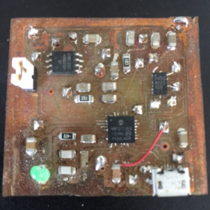
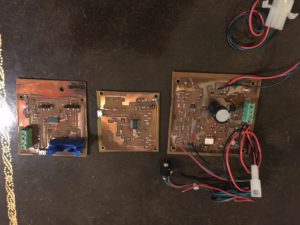
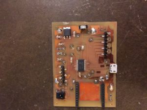
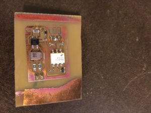
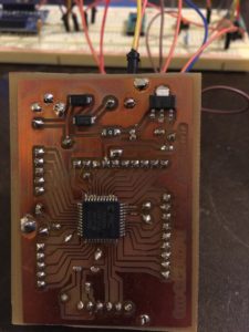
Making your own printed circuit boards is not too hard….but it is time consuming and you’ll need some equipment to get started. I’ll say this up front. Unless you consider your time completely free or have some really good reason, pay to have boards professionally done. They can be made more dense, are higher quality, and allow things that you can’t do at home like silk screening. At this point, the only time I make my own board is A) I need (want) it quickly or B) it’s a prototype that I’m afraid may not work just right. These days almost everything is surface mount, so sometime things can’t be easily bread boarded. In that case I may make a board. Otherwise, I send my design off (to China) and usually get 10 boards back ~2 weeks later for around $25. Of course I must still solder components (you can pay to have that done too), but I find that quite a bit easier and more time efficient. Here are a few that I’ve done myself:
Regardless of how you get your boards made, you’ll need to do a PCB layout. I use the Free version of Eagle. It only has two real limitations. 1) the size of the boards you can make are 80mm x 100mm (3.15″ x 3.93″) maximum. On a few occasions it’s cost me some time getting the PCB layout optimized enough to get down to the size restrictions, but generally it’s been no issue. The second limitation is that you can only do 2-layer boards. Given that this is about fabricating your own boards, a 2-layer limitation is a non-issue. Even the boards I’ve had professionally done are only 2-layer, so that Eagle limitation is not a concern for me. I’ll talk more about some of the Eagle guidelines I like to use in a bit.
Next is actually etching the boards. Etching is not too bad in terms of time, but it does take a fair amount of equipment and practice. The worst part are the chemicals. Etchant is pretty expensive. There are several types but it’s all nasty stuff that should be disposed of properly. The most important part of the etching process in my opinion is consistency. Once you find a formula (steps, exposure times, etc.) that works for you – follow it exactly every time. I’ve trashed a few boards and it’s always because I skip a step.
After etching comes the worst and most mind numbing part….drilling the vias and through holes. Each via must be drilled, have a wire fed through, and soldered on both sides. It’s a complete pain to do. The hard part with all the drilling is getting things exactly lined up…I’m talking 1000ths of an inch here. If you have a 20 pin (2 rows of 10) connector on .1″ centers that must feed through the board and be soldered, imagine if each hole is offset by +/- .025″. It makes it very difficult to get components through the board. You must almost manually bend each pin. Very ugly. The solution I use is a mini drill press with a small x-y table (more on that below). It allows me to move very accurate distances and drill at a 90 degree angle. It is still very time consuming though.
After drilling comes populating the board. Some people use solder masks, and I’m sure they save a ton of time, but for the low volume stuff I do, I simply place solder paste on the pads, set the SMT components, and put it in a toaster oven. Actually, I just got through with a sprinkler controller board. It had a lot of components and took 4-5 hours to get the solder paste on. Next time, I’m ordering a stencil to try (maybe a post on that). After the SMT components are set in the oven, I come back and do the hand soldering and vias. That’s all there is to it.
Okay, starting with equipment needed. The equipment is where you’ll need to invest some money and/or time. Here’s what you’ll need.
- Light box. I built my own. More on that later.
- Etching tank & air pump. Built my own. Buy one or see how I did it later.
- Microscope (optional)
This is optional, but I personally could not work without this. I bought a cheap AmScope SE400-Z (see picture) from Amazon. I think I paid $179 for it. The model I have does NOT have the LED light like the one pictured. Instead it has a small light bulb that get hot and burn out often. I’m convinced the LED design would be excellent to have and maybe I’ll retrofit someday.
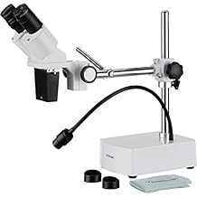
Otherwise it works great! I use it all the time for different tasks.
- Drill & Mini drill press (Optional)
Again, I suppose this is optional, but I use the the Proxxon drill for several tasks. I use a cutting wheel to actually cut my PCB boards. I use it to drill (obviously), and I used the drill press and x-y table to position the board and get accurate drilling. If you’re cheap like me, the thought of spending $275 on a drilling setup is hard to swallow but it makes your results a lot better and I personally use the drill press and x-y table for lots of things besides PCB boards. Note: cool project would be to put the x-y table on stepper motors and then send the Eagle drill file to a microcontroller and have it drill all the holes automatically.

Professional Rotary Tool IBS/E ($120)
 Cut Off wheels (Home Depot)
Drill Stand MB 140/S ($69)

MICRO Compound Table KT 70 ($95)
- 5. Misc: Plastic containers, high speed cutter, etc.
Now that you have the tools you need it’s time to get started.
First a few words about Eagle spacing. I personally work in mil (1mil = 1000th inch) settings, although I keep considering going to mm settings. I generally work in a 20 mil grid spacing and use 15mil wires and try to keep at least one grid point difference between wires (40 mil center to center, or 25 mil between wires). If I need tight spacing I go to 30mil spacing and put wires on every grid row (30 mil center to center or 15 mil between wires). Many of the PCB manufacturers can do 6mil width and spacing or better.
Once you have a design complete, it’s time to print the artwork. More on that in part 2. Stay tuned.