Now to get to some hardware. But first, let’s revisit the data packet structure. The last time I think some of the values were for the 4.0L. This includes the 2.5L layout (which I’ve mostly verified)
| 2.5L Engine Code Locations | 4.0L Code Locations |
| [0] – ECU Program Version (Constant). If = 32, then it’s 2.5L, if 177 then 89-90, if 176 then 87-88 | |
| [1] – ECU PROM version (Constant). If 16 or 20 then Auto, if 144 or 148 then Manual, if 98 then new, 97 = mid, 225 = old. | |
| [2] – Various AC Bits and Throtttle position (Note Throttle is fuelsync on 4L) | [2] – Calibration Code from engine |
| [3] – Raw Manafold Absolute Pressure. Convert To inHg Map = MapRaw/9.13) + 3.1. Convert to volts Map = MapRaw/51 (Volts) | |
| [4] – Coolant Temp. Reading/0.888) – 40 – Coolant Temp Sensor in F | |
| [5 ]- Inlet Air Temperature (Reading/0.888)-40 – Inductive Aitr Temp F | |
| [6] – Charging Voltage (Reading/31.875)+8 – (2.5L) Charging Voltage Vdc | |
| [7] – Reading*4.34 – O2 Sensor reading in volts | |
| [8 Low Byte][9 High Byte] – Engine RPM 19868686/((High Byte << 8) | (Low Byte) * 1.5 | Don’t multiply by 1.5 |
| [10] – Injection Pulsewidth Low | PROM |
| [11] Injection Pulse Width High. InjPulseMs = (High Byte [11] << 8) | (Low Byte))/1000 Injection Pulse Width ms | PROM |
| [12] – Reading / 2.55 – Throttle Position Sensor (% Open) | |
| [13] – Spark advance in degrees | |
| [14] – Unknown | |
| [15] – Unknown | |
| [16] – Initial Manafold Absolute Pressure inches Hg | |
| [17] – Unknown | |
| [18] – Bits indicate fuel control mode (open/closed) and if we’re in rich or lean condition | |
| [19] – Unknown | [19] / 7.79 – injection pulse width (milliseconds) |
| [20] – Unknown | |
| [21] NOT USED on 2.5L | [21] – Used to determine if we’re under close, partial, or wide open throttle – |
| [22] – Unknown | |
| [23] – Unknown | |
| [24] – Short term fuel trim. This is the amount of fuel being +/- to the base fuel curve. < 128 then subtracting from base | |
| [25] – Unknown | |
| [26] – long term fuel trim – Long term average of STFuelTrim | |
| [27] – engine knock sensor – low value is normal and increases with RPM | |
| [28] Unknown | |
| [29] AC Switch | |
Again, some of the bytes need to be decoded:
| 2.5L Engine | 4.0L Engine |
| Byte 2 Decode: | Byte 21 Decode |
| Bit 2 AC Switch on / off | Bit 1 Bit 3 ThrottleState |
| Bit 3 & 4 = Throttle Position | 0 0 Partial |
| Bit 5 = EGR ????????????????? | 0 1 Closed |
| Throttle Position: | 1 0 Wide Open |
| Bit 3 Bit 4 ThrottleState | 1 1 Partial |
| 0 0 Partial | If (Bit 1 XOR Bit 3) Check Bit(4) to determine Closed or Wide Open Otherwise it’s Partial |
| 0 1 Closed | |
| 1 0 Wide Open | |
| 1 1 Partial | |
| If (Bit 1 XOR Bit 3) Check Bit(4) to determine Closed or Wide Open Otherwise it’s Partial | |
| Byte 18 Decode | Byte 18 Decode |
| Bit 7. Set = Rich, else Lean | Bit 7. Set = Rich, else Lean |
| ECU Control Mode: | ECU Control Mode: |
| Bit 1. Set = Decel Mode (not in closed loop) Otherwise | Bit 1. Set = Decel Mode (not in closed loop) Otherwise |
| Bit 6. Set = Closed Loop, otherwise Open Loop | Bit 6. Set = Closed Loop, otherwise Open Loop |
Now for the hardware. In Part 1, we went through the interface circuit which took the ECU signal and shifted it to a 3.3V signal.
My plan was to take the ECU serial signal and pull it into an ESP8266. If you’re not familiar with it, it’s a very inexpensive, Arduino compatible, microcontroller that has a built in WiFi module. It has many libraries that provide some pretty sophisticated functionality including SSDP, UDP, TCIP, etc. It can act as a web server and has a wide range of other utilities like JSON string builder etc. One of the cool things is that you can start the WiFi in Access Point mode. This gives it it’s own SSID and requires no other infrastructure. So in other words, you can be in the middle of nowhere, pull out your phone or computer and hook into the data reader, and go on indefinitely receiving data under a wide variety of conditions. Cool!
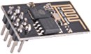
ESP8266 – <$7 from Amazon and many others.
Originally I planned to interface the ESP8266 to a PIC32 (which I did on an IoT Sprinkler Controller). The PIC provides lots of memory, I/O, and a much more robust development/debug environment (to name a few). I had planned to interface accelerometers, fuel pressure sensors, etc. but decided against it. Against all other urges to make the scope really big and complex, I decided to keep it as simple as possible….and maybe expand it someday.
Sooooo, my plan was to use the ESP8266 as an Access Point, connect to it with my computer or phone, and make simple HTTP requests to get the ECU data. I wanted to provide the data in a JSON format since many Web Browser (Chrome, Fire Fox, others?) have plugins that format the data so that I could use a simple web browser to look at the data if desired. On top of that, I planned to develop a C# Windows Forms (yes I’m lazy) application to enable the data to be displayed and logged at any desired rate.
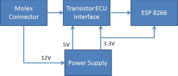 Block Diagram of Circuit
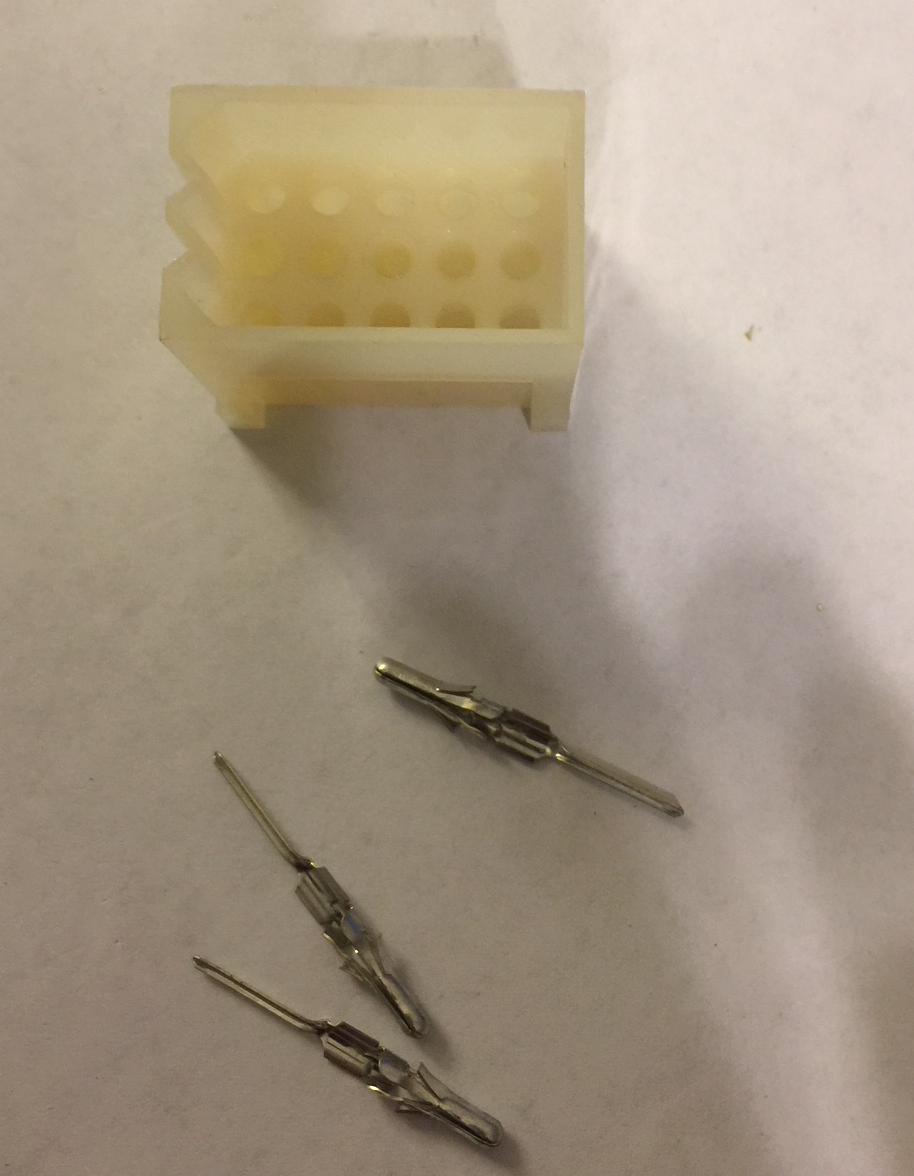
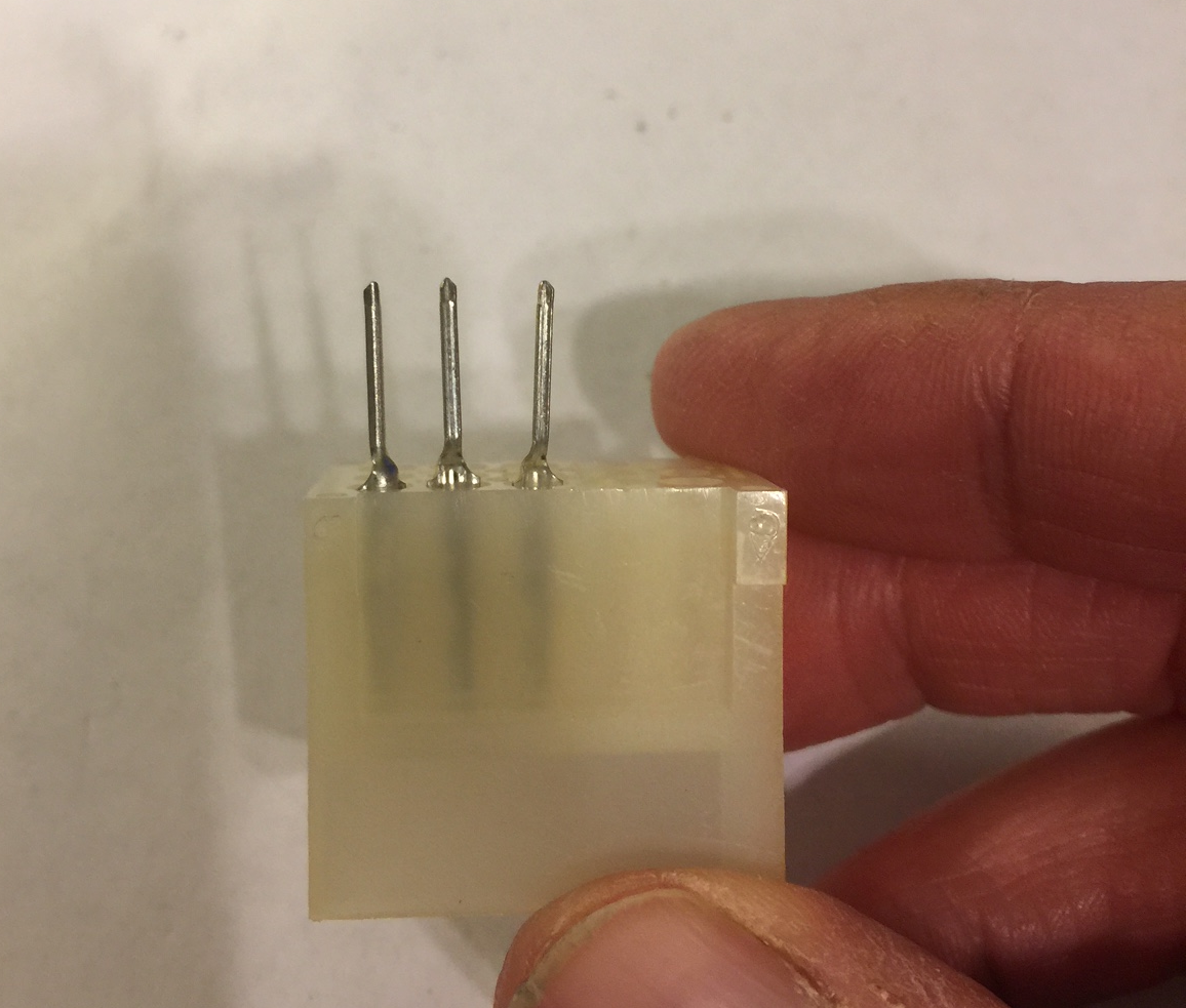
As I said in part 1, I think the Molex connector is Molex PN 03-09-2151, but I’m not sure. I found them at a local electronics surplus store. I wanted to mount the molex connector directly to the circuit board so the Molex pins were a key piece. They are part number 02-09-2134 “Male PC Tail” pins. Instead of a wire crimped to the pin, the pin protrudes through the circuit board and is soldered in place.
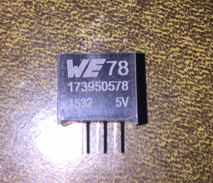
Here are some pictures of what they look like:
The next area is the power supply. I planned to run on the Jeep power (~14 Volts). From that I need to drop it to 5V and 3.3V. The ESP8266 can take several hundred milliamps when it is transmitting, which can amount to quite a bit of power wasted as heat going from 14V to 5V. Therefore I opted to go for a switching power supply. My first prototype of the board used a standalone designed switching power supply. It required an IC, inductor, diode, and capacitors.
First revision of power supply.
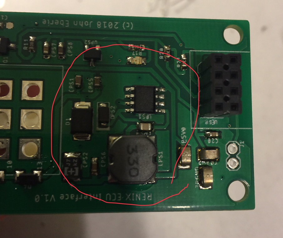
I had a couple issues with the first revision and was doing some breadboard testing. I wanted to build a switching power supply for the breadboard so I’d have an exact copy of my final circuit. Unfortunately, getting all the components I wanted in through hole was going to be a pain. It was then that I found the Wurth #173950578. It is a standalone 3 terminal switching power supply. It claims to have all of it’s own input and output filter capacitors already integrated. It has a very wide input voltage range and up to 200mA of current capability. It comes in 5V and 3.3V versions.
Let’s see….less board space, less stuff to solder, and cheaper than doing it with discrete components (about $4.50). That was a no brainer. So I feed the switching regulator through a resettable fuse and polarity diode (optional). I also added a TVS diode and filter capacitor on the front end. From the 5V switching supply, I feed a 3.3V linear regulator. I provide a small amount of filtering on the input and output of the linear regulator. I included a ton of test points which I normally do on a prototype. I already covered the ECU transistor circuit (and the 150 Ohm resistor to gnd). I also put an LED on the EGR signal output of the Molex connector. I placed this LED there so that I could watch the EGR function while looking at the engine. My rationale was that it’s an old Jeep with a lot of suspect vacuum connections. I wanted to get a visual indication of when the EGR was being activated so I could look for a correlation between vacuum leaks and engine performance. I’m not sure how that’s going to work out for me…..
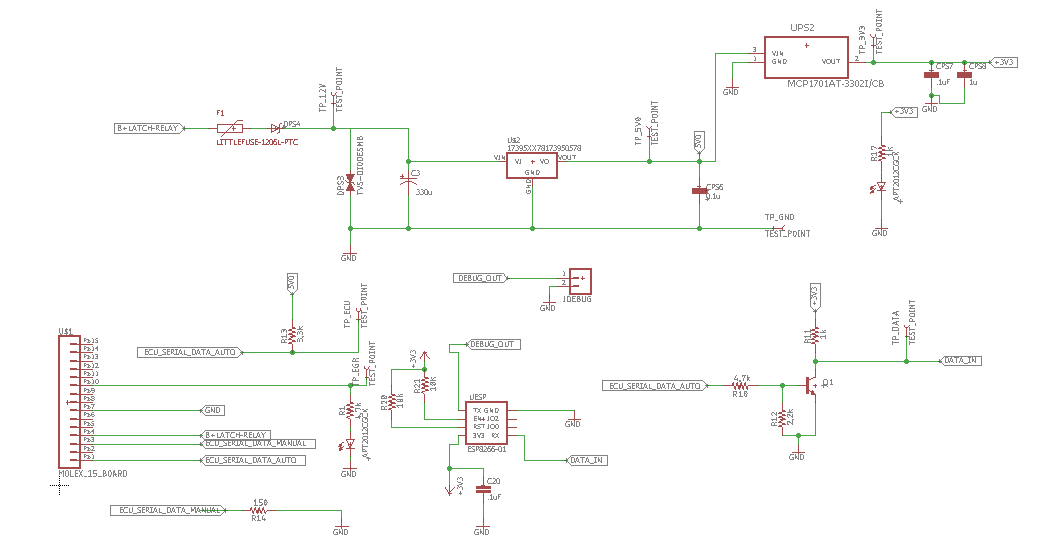
The ESP8266 has one serial port and I use the input for the serial ECU data in. I use the output for debugging. I can hook up the TX pin to a header and bring it out to hook on a serial monitor, serial to USB converter, or whatever. That’s a nice feature when debugging.
Here is a link to the Git Hub files including:
- The Eagle schematic and board files.
- The BOM in Excel format
- The ESP8266 c code in Arduino sketch format.
- The C# project for the logger.
https://github.com/jeberle5713/JEEP_ECU
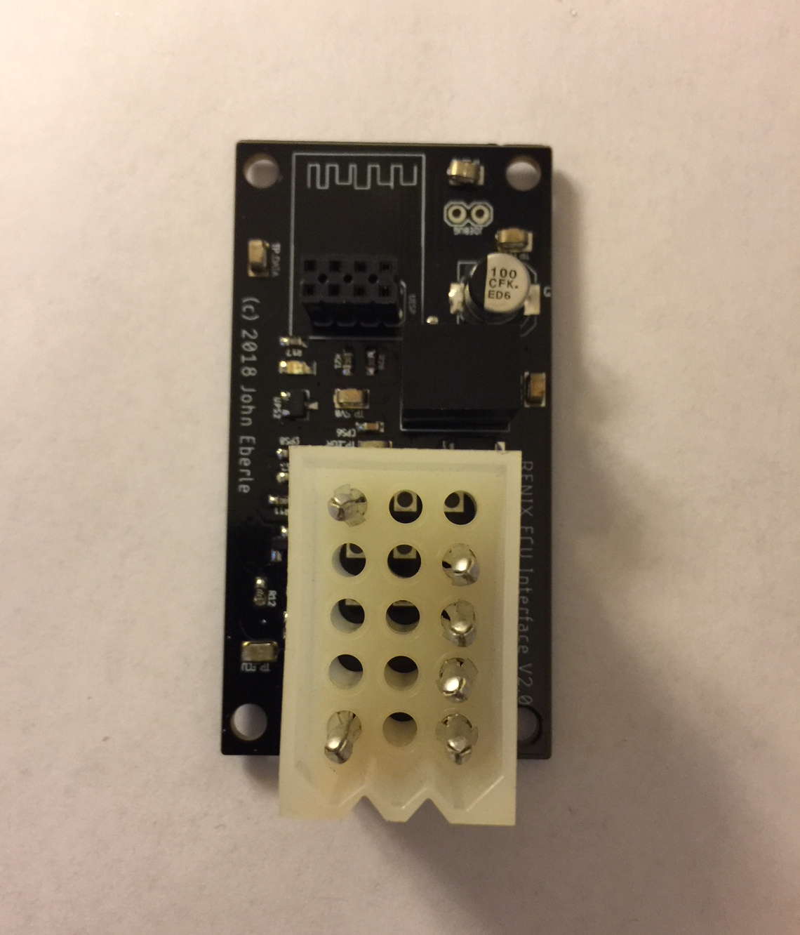
Here’s a picture of the board after I finished mounting the SMD’s on it. Unfortunately, I got excited and soldered the Molex connector on the wrong side of the board. Ooops.
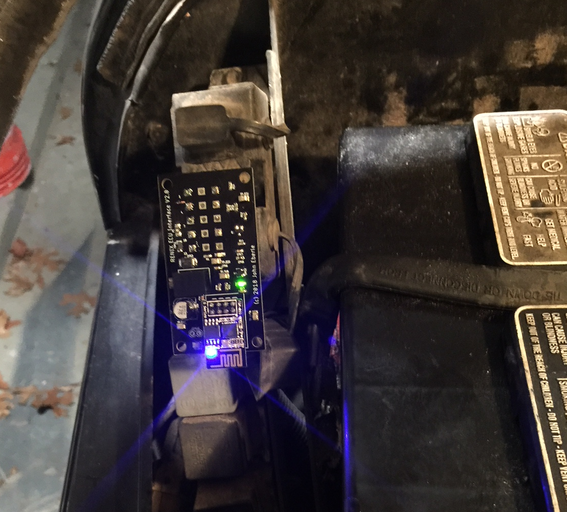
And here’s another picture of it fully assembled and in place on the Jeep. Yes, I turned around the connector.
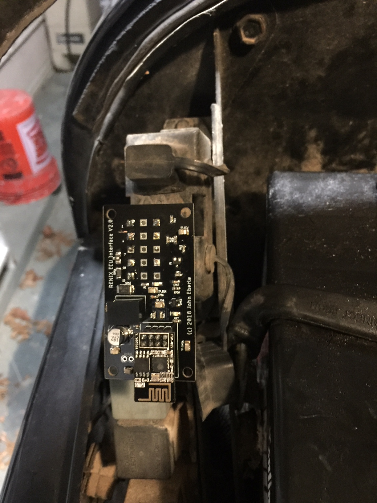
Turning the ignition key to the accessory position will energize the board and the ECU will start to send data.
To see and log the data using the C# application, first start the Jeep Rennix ECU Reader application. Make sure the molex connector is connected to the Jeep and it is either running or in accessory position. You should see a green power light on the board (The blue light on the ESP8266 may also be on).
Next, select the RenixECU SSID for your WiFi.
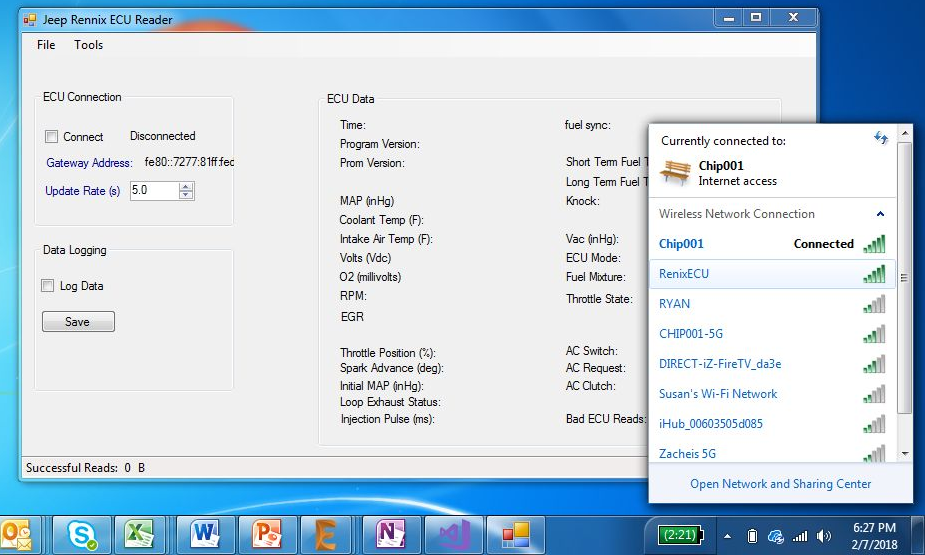
If successful, you will see the IP address of the ESP8266 show up on the screen where it says “Gateway Address”. For me it’s 192.168.4.1. You can use that address in a web browser to see realtime data by going to the web page: http://192.168.4.1/ecu.
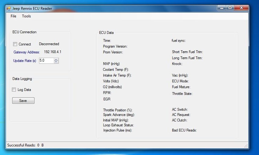
When you’re ready to connect, select the “Connect” check box. When everything is okay, the status will change from “Disconnected” to “Connected”. You can change the communication update rate using the Update Rate up/down arrows. Default is 5 seconds. I usually take this down to 1 or 2 seconds, but if you were doing a long highway cruise, 10 seconds or more might be okay.
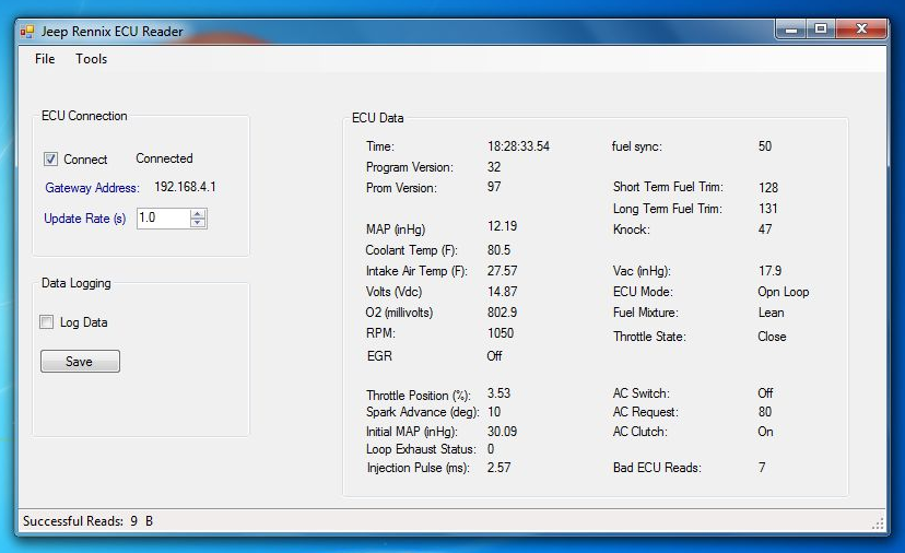
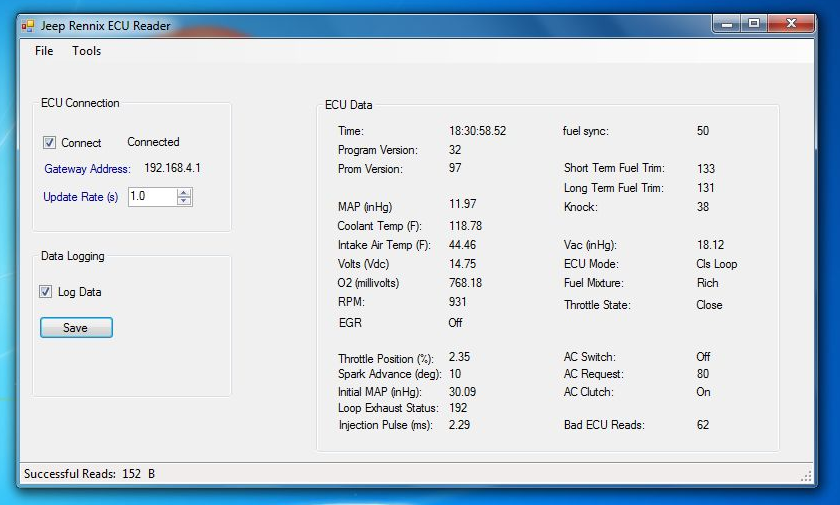
Once you’re connected and have the update rate set you’ll start seeing data on the screen. It isn’t being logged until you check the “Log Data” check box. Logging will then start or stop. Note: you can log for a few minutes, then uncheck the box to stop logging, then check it again to restart. When you’re ready to save it, hit the save button. You’ll also be prompted to save data when quitting the application if it needs it. Also note, the logging is progressive. If you save data after 5 minutes, then run for another 5 minutes and save again, the first log will have the first 5 minutes and the second log will have the first 5 minutes AND the second five minutes.
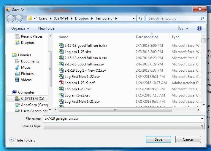
Data is saved in a CSV format to enable it to be imported into a range of software.
There’s currently a problem with the application if you shut off the jeep with the logging running. It will take a very long time for the application to respond. It is simply trying to communicate with the ECU. The proper shutdown procedure is to stop logging, then disconnect, then stop the Jeep or exit the App in any order. I’ll fix this in a later version.
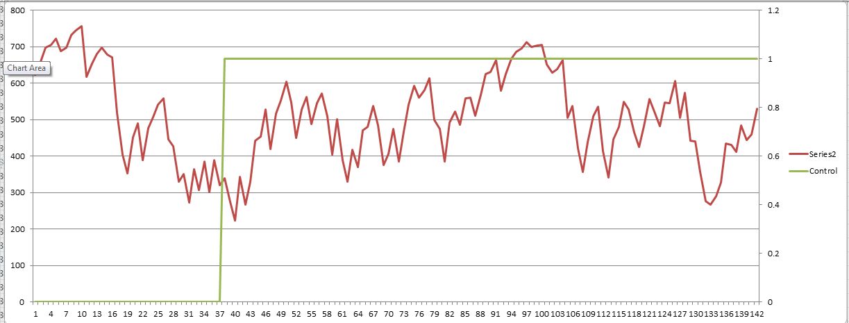
So what did the data tell me? Plotted below is the O2 signal in red and the ECU control mode in blue.
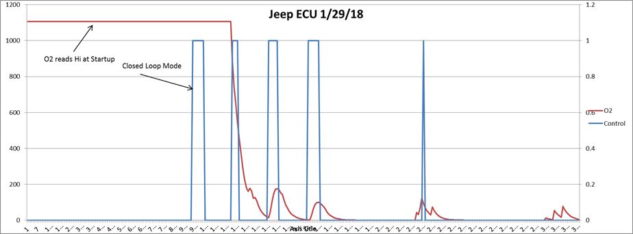
Initially the O2 sensor reads high. This is not unusual because the sensor must warm up before operating. The ECU tries to go into closed loop mode at reading ~99 (the coolant temperature is just > 100F – not shown), however the O2 signal doesn’t respond. Looking into the data I could see the short term fuel trim going to zero as the ECU tried to lean out the mixture. At this point the engine would begin running poorly (way too lean). Next the jeep computer would give up trying to stay in closed loop mode and return to open loop mode. At about data point 120, the O2 reading suddenly goes low. The ECU seems to sense it and again tries to go into closed loop, but this time the O2 reading stays low (it should hover about 500 when the AF mix is correct). Now the short term fuel trim goes to max as it tries to richen the mixture. Again it gives up and goes back to open loop mode. After taking quite a bit of data I found that my jeep stalling/bogging issue happened as the ECU was trying to run in closed loop mode (not surprising). Once the ECU gave up, the jeep ran okay…and was in open loop mode all the time. So what was the fundamental problem?
Well, I asked Moses Ludel at 4WD Mechanix magazine forum: https://forums.4wdmechanix.com/topic/1071-1990-jeep-yj-25-tbi-stalling-during-warmup/?tab=comments#comment-7304
Again, similar to Nick’s work on the code reader, here’s a guy who’s happy to help out others with his knowledge. Moses gave me a few ideas. First and foremost (and easiest) was the O2 sensor (duh). So I replaced it. The OEM was a NKG unit.
This time the O2 sensor responded much faster. After the jeep warmed up and the O2 reading dropped, the ECU kicked into closed loop. This time it stayed there. You can see from the graph below that it then controls around mid-point as expected. Problem solved!
Now onto my next project. Pulling the oil leaking engine out and rebuilding it. Oh, and I’m starting to look at an IoT garage door monitor system. I have some cool ideas around some 433Mhz short range data communication for the sensors. I’m now in the process of learning about pcb antennas. Fun!!