Awhile back, we bought a ’90 Jeep YJ just to drive around the ranch and into town.

It’s nothing too special, only having a 2.5L 4 cylinder engine and manual transmission. It didn’t take long to realize that it had a few problems. The worst is a really bad oil leak. ….I mean a quart of oil on the garage floor kind of leak coming from the rear main seal. The second issue actually bothered me more. The jeep would start fine and warm up well, but then it would suddenly sputter and die. After asking around and consulting the internet, I was pretty sure that it was a bad O2 sensor and after the engine went through it’s open loop warm up sequence and switched to closed loop the problems happened. No problem! Just hook up an OBD II diagnostic reader, check the engine codes, and it’ll be obvious what needs to be fixed – Right? Wrong! From the time jeeps (and many others) started getting computer systems until about the mid 90’s the systems were proprietary and required special tools to read their diagnostics ($$$).
The oil leak sucks, but I know how to fix that. In my case I’ll be pulling the engine out and dropping in a rebuilt one…but that’s for a later post. The thing that kept me up at night was thinking about dropping a couple $k on an engine and having an intermittent problem that I couldn’t find. I’ve been there before, replace this part and hope it’s fixed. Nope. Replace another part. Nope. Rinse and repeat. Which got me to ciphering, which is usually a bad sign. How hard could it be to build my own diagnostic code reader?
Turns out it’s not too hard. Well, actually it’s damn near impossible unless some folks have cracked the code already. In this case, I came across this web site: https://www.facebook.com/nickintimefilms/
Turns out Nick has done most of the ground work already and has an Arduino based open source design and software published. He also has a bunch of YouTube videos showing how he figured out some of the various things. No way I would have spent the time to figure all the different intricacies out. If you’re reading this and interested in buying something (kind of) off the shelf, he offers some very inexpensive boards (when he has them in stock) that do a lot more than just read ECU codes. His stuff also works on different engine and transmission combinations which, as it turns out, each have some of their own differences. He and I spent some time IMing at one point when I was having some trouble and he really helped me out. I can’t say it vehemently enough…He is the man and deserves 90% of the credit.
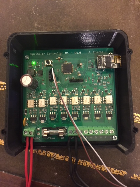
But, why buy something off the shelf when you can spend way more time and money doing it yourself I always say. So I decided to try to build my own ECU reader. I just spent the last 5 months building a IoT smart sprinkler system for my Samsung Smartthings/Alexa system at home and fot the Ranch (Perhaps a long project post on that sometime). For that system I used an ESP8266 WiFi module to communicate with Smartthings and interfaced it to a PIC32MX processor. I think it’s really cool sitting in my snazzy 3D printed case. In fact, it’s watering my yard as I write this.
But, back to the Jeep. So, I planned to do a similar system. I’d use the PIC to read the Jeep ECU data then send it to the WiFi module to act as a server. I could write a slick custom reader/logger in C# and if all else failed use a web browser to get the data in a JSON format, which I could do from my phone or whatever. And that’s exactly what I’ve done – kind of. Turns out I haven’t used a PIC at all. I simply use the ESP8266 to read the data and act as a server. Having the PIC would have been great, and a future iteration may have it. It would have allowed a bunch of I/O options and some analog capability, but all that extra capability caused the project scope to rapidly expand. All I really need is the ability to read the ECU and get the diagnostic data. I have way too many other projects (like swapping the Jeep engine) and want to get something quick and dirty.
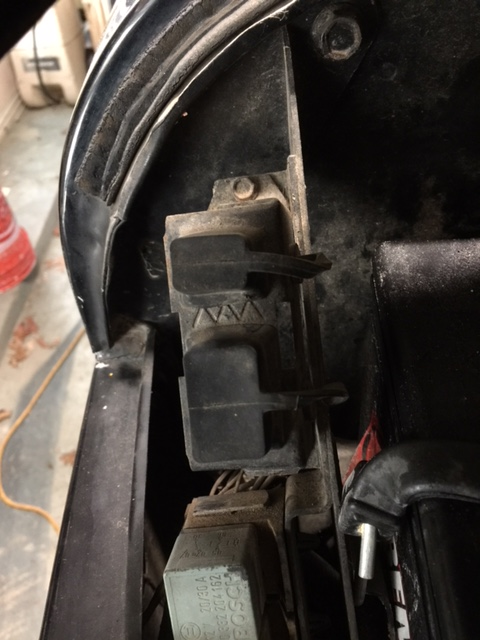
Problem #1 getting the ECU serial data. The Jeep has two diagnostic connectors on it. They are located on the passenger side (is that left or right…I can never decide).
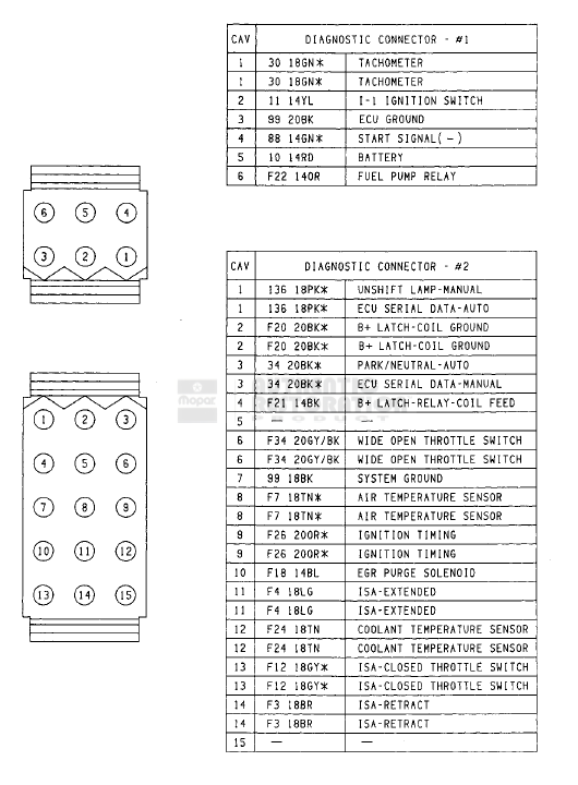
The 15 pin connector is the one we’re interested in. Turns out Pin’s 1, 3, 4, and 7 are the key ones.
I believe the connector is a Molex 03-09-2151 but I’m not completely sure. I was able to find a bunch of them at a local electronics store. The pins can be standard Molex .093” male, which is exactly what I used.
Power (12Vdc) is on pin 4 and ground is pin 7. Simple enough.
Reading the chart it says:
Pin 1 is ECU serial data – auto
Pin 3 is ECU serial data – manual
That sounds easy. For a auto transmission use pin 1 and manual transmission use pin 3. Right? No! It’s really an odd setup. Best I can figure out after looking at the Jeep wiring schematic is that with an auto transmission the ECU uses pin 3 as a park/neutral input but with a manual system, it must be grounded to get the ECU diagnostics to work correctly. Nick did a video on this here: https://www.youtube.com/watch?v=sNr1_FT9_E4 It’s a long video but you’ll learn a lot from it.
So pin 1 is ECU data with auto or manual. The difference is that with a manual, Pin 3 must be grounded. ….I wouldn’t have figured that out in a million years.
The ECU data pin (pin 1) is an open collector output. Something like this:
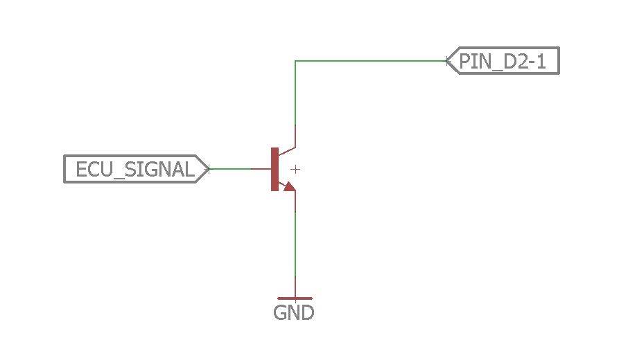
So to interface to the ECU, we pull up the collector with a resistor to our power supply and then use input as our ECU signal like this:
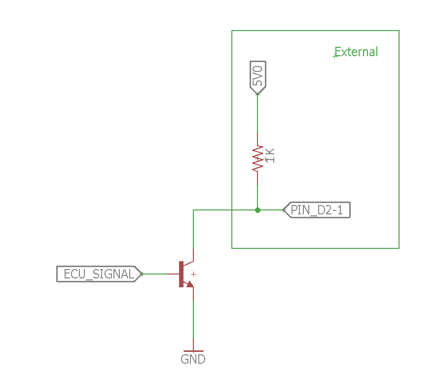
Notice that this is an inverting arrangement. When the ECU signal is high, the transistor turns on and so the output signal voltage is 0 (actually Vce across the transistor). When the ECU signal is low, the transistor is off and so we read 5V. Well that’s easy to interface to – right?
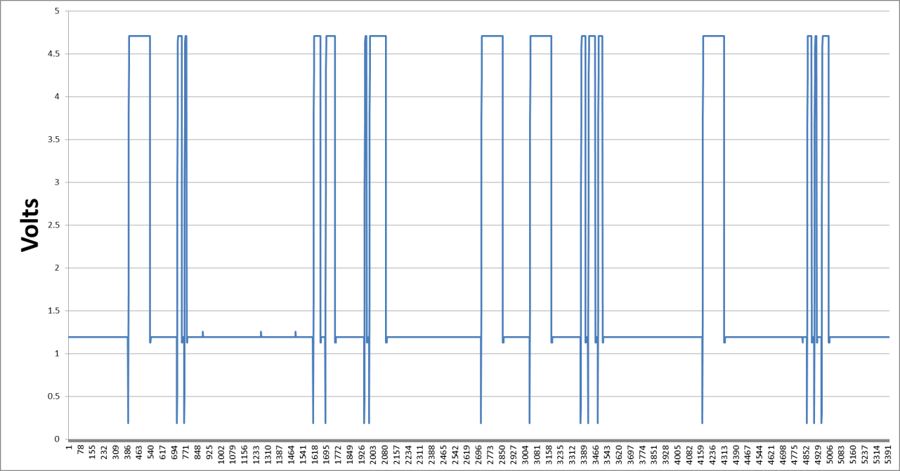
The next figure shows an oscilloscope trace when hooked up as shown above. The serial data is clearly visible, however the input signal is riding at roughly 1.2V in a low state. Why it’s that way is a mystery to me, and there’s no good way of knowing without really understanding the circuitry inside the Jeep ECU. Supposedly that bias is not there for auto transmission version, but I can’t personally confirm. It really doesn’t matter.
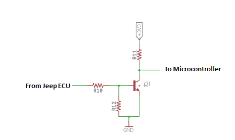
The implication to this situation is that an input circuit needs to be designed which “sees” 1.2V as low and something >> 1.2V as high. Ideally, we’d have a switch that switched state at ~ 2.5V. Something like this circuit with a simple voltage divider at the input.
So, when the ECU is at 2.5V, we want the Base-Emitter voltage to be roughly 0.7V to turn on the transistor. The equation becomes:
Then neglecting Q1’s base current:
2.5 = (R10 + R12)x(0.7/R2)
Then, R10 = 2.57 x R2
Using standard values, a good selection is: R10 = 4.7k and R2 = 2.2k
The value of R11 is not very critical and simply needs to limit the collector current when the transistor is on. The 2n3904 datasheet says it’s good up to 200mA. The key thing to note is that it’s hfe and turn on time both improve as the collector current goes up. Picking a collector current 1-10mA is a good choice, especially since this won’t be a battery powered application. A resistor of 1k will keep the current to around 3mA. Here’s the input circuit with pullup (R13) included.
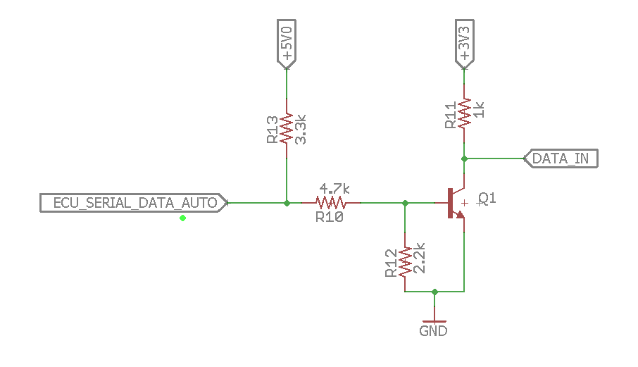
Notice that the pullup resistor on Q1 is 3.3Vdc. This is the input voltage required for the microprocessor, but 5Vdc is being used as the pullup for the Jeep ECU. It would be nice to have both voltages be the same. I did some preliminary work using 3.3V as the pullup for the Jeep ECU and got poor results. I didn’t go any further (yet) in the interest of getting something working! I’ll go into the power supply later, but it’s pretty easy to add a linear regulator to the 5Vdc supply to get 3.3Vdc.
Remember, I said earlier that the ECU Serial Data Pin – Manual (D2-3) had to be tied to ground? Well, I tied it to ground through a 150 Ohm resistor just to be safe.
Here are some pics of the setup:
Jeep Diagnostic plugs on passenger side firewall.
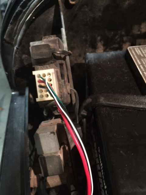
Molex connector plugged into JEEP ECU 15 pin diagnostic port. Pin 1 is top left. Pin 3 is top right and so on. You can see that I am using:
Pin 1 – ECU Serial data – Auto. Green Wire.
Pin 3 – ECU Serial Data – Manual. White wire.
Pin 4 – Battery relay. Red wire.
Pin 7 – Ground.
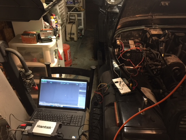
Getting started with breadboard visible (on the fender) along with a laptop, Hantek oscilloscope, and Saleae logic analyzer.
The data coming out of the ECU is a nonstandard value at 62500 Baud, otherwise it’s pretty standard (no parity, 8 bits, 1 stop). Here’s a shot of my logic analyzer output:
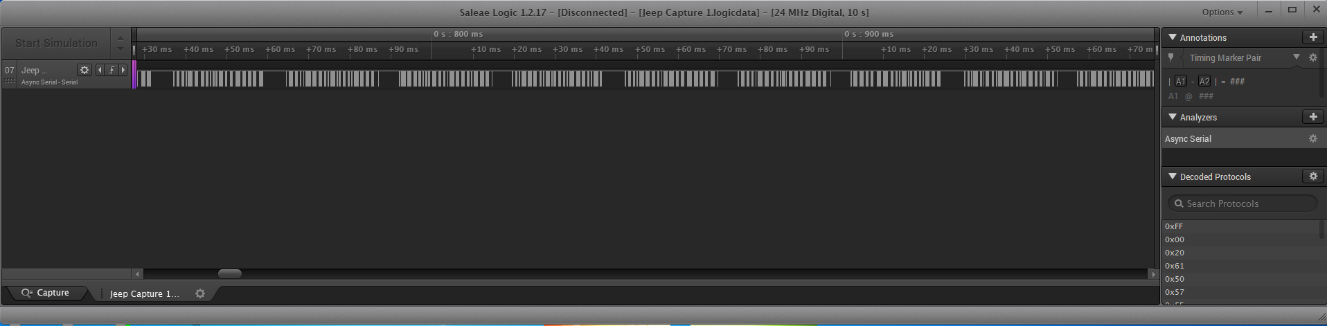
Next post, I’ll start talking about data packets and more hardware!